TURBO – Build to Spin: The Design of a Motor Driver Board
On previous rover designs, we relied on third-party motor driver boards to control components such as the motors in the deep sampling unit. In this iteration of the Rover, we aimed for a more self-sufficient and scalable solution by developing our own motor driver board, capable of handling both BLDC and servo motors. The board was designed with reusability in mind and is intended to support a wide range of future applications.
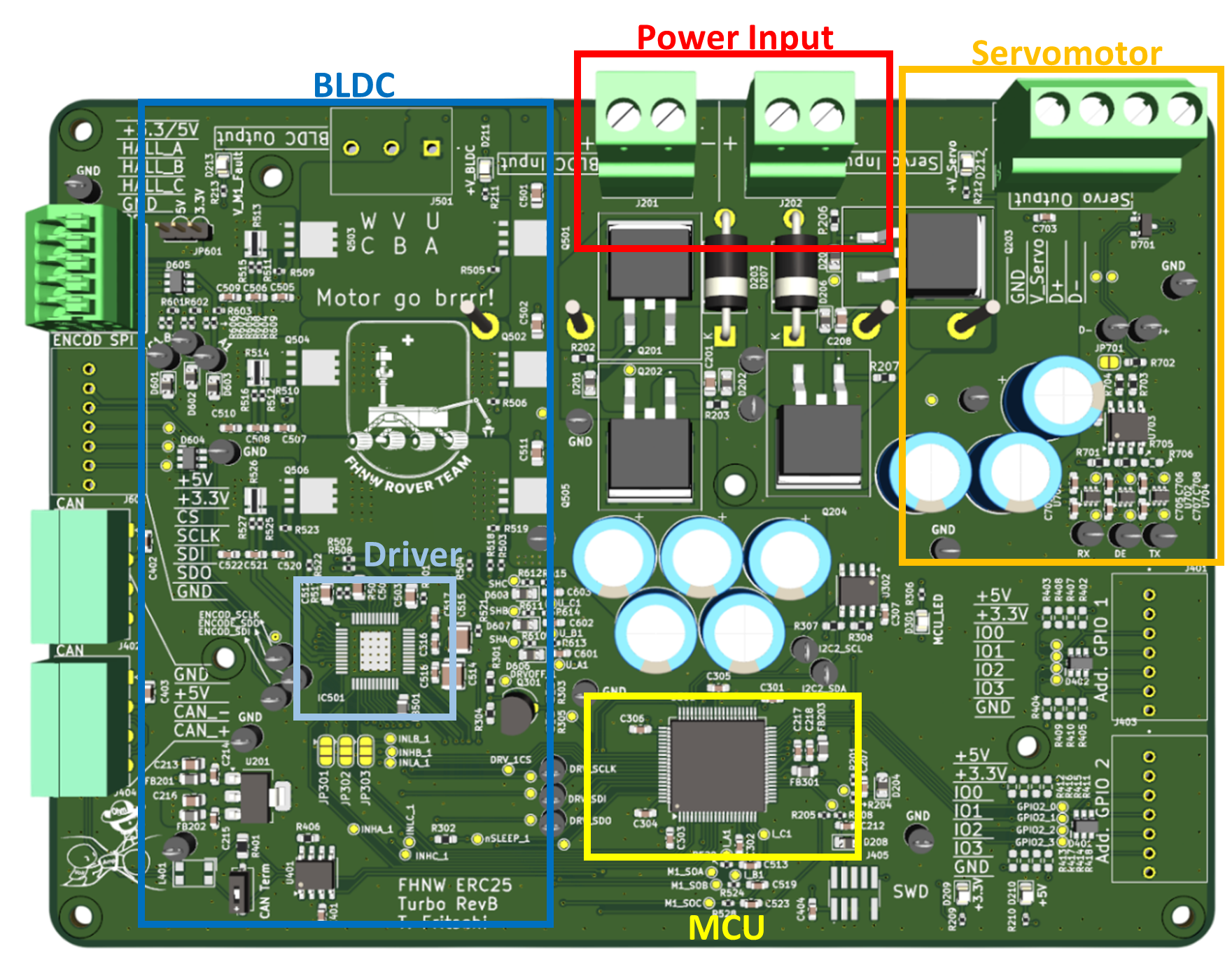
BLDC motor for drilling:
At the core of our BLDC driver section is the DRV8334 from Texas Instruments. With its wide operating voltage range from 4.5 to 60 V, it supports various motor configurations and significantly increases the board’s versatility.
Key advantages include:
– Phase current sensing for precise speed control
– Extensive fault protection and safety settings
– Multiple configuration options for commutation
For the power stage, we selected suitable MOSFETs for both the high side and low side. The main challenge here was thermal management, due to the high switching frequencies involved.
Servo Motor for Positioning:
In Revision A, both the drilling and positioning tasks were handled by BLDC motors. However, in Revision B we switched the positioning motor to a servo motor after discovering an ideal solution from Dynamixel. This change brought several benefits: the new motor is lighter, more cost-effective and comes with an integrated encoder.
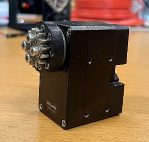
This change required a complete redesign of the right side of the PCB. While the BLDC motor operates at 18 V, the servo motor requires 24 V. To support communication, we also added a UART to RS-485 transceiver.
Expandable Logic:
To ensure long-term flexibility, the board includes interfaces like GPIO, UART, and I2C. This makes it easy to connect additional devices in the future.
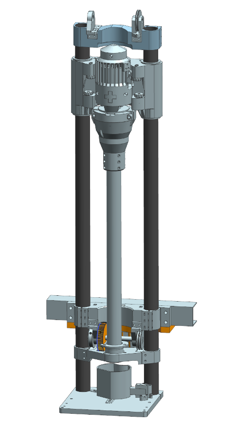
Mechanical Design:
The following picture shows the current mechanical design developed by one of our mechanical engineering students.
The next steps are to finalize the firmware implementation and to carry out a full system test under real drilling conditions. This will include evaluating the performance of both the BLDC driver and the servo motor.
If everything goes as planned, the system will be tested in our newly built Mars yard environment!
Comments
No comment posted about TURBO – Build to Spin: The Design of a Motor Driver Board