Modified CAD and 3D-print
Reconstructing historical instruments with CAD and 3D-print
By Ricardo Simian
3D-print is a set of new technologies which allows direct transformation of computer 3D-models into real objects. As opposed to common understanding, 3D-print is not a single type of technology (there are many different kinds of 3D-printers based on very different procedures) and 3D-printers can’t do everything (although they become capable of doing more things by the day). Navigating this matrix of continuously evolving technologies and finding the correct combination between type of printer, material, size, density, detail, smoothness, porosity, flexibility, colour, resistance, post-processing, curating, polishing method, coating and budget in order to produce a specific object is a very tricky task. This endeavour is what I have taken on as a goal in order to deliver innovative solutions for research, development and production for cultural, design, artistic and musical projects through the development of the Basel startups 3D Music Instruments and Simply D3sign.
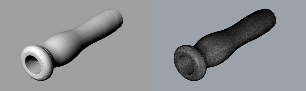
The „fagottini“ project is a fine example of applied research within music. This instrument has been forgotten and mostly relegated to museums for more than a century, despite consistent proof of their use both in written music and in the many surviving examples. The traditional approach of bringing a forgotten instrument back to performing life is long, treacherous and expensive, requiring many successive tests on many hand-made copies, which generation-by-generation accumulate a consensus of satisfaction high enough to support the use of the resurrected object. This has been done since the 1950s for most Renaissance and Baroque musical instruments, though a decade-long process, with different degrees of success and accuracy. Through the wise use of 3D-print we can markedly accelerate this process, making it more affordable and raising the standards of accuracy far above what hand-made copies can ever offer.
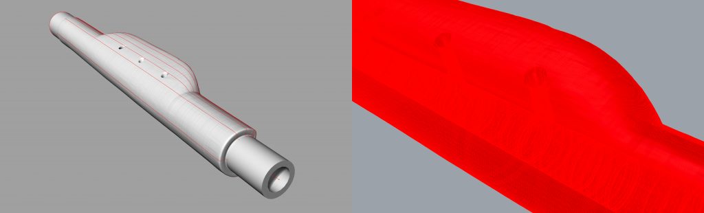
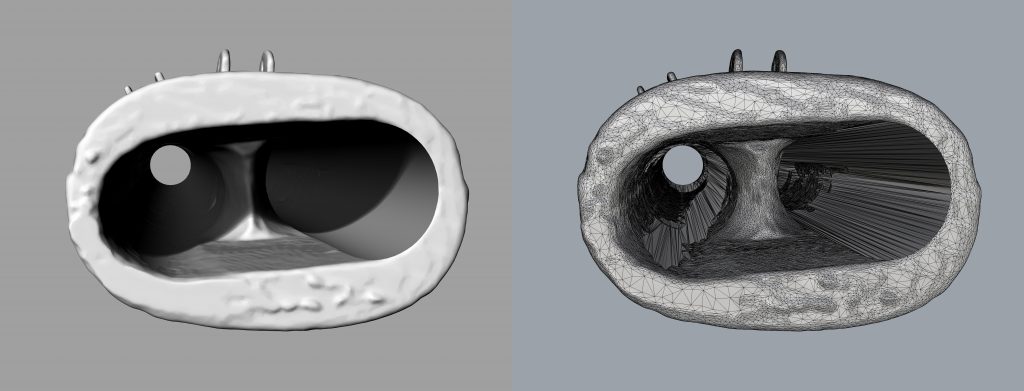
The original fagottini have been measured both manually and with computer tomography scans. Based on these data sets, there are at least two possible approaches to making 3D-print copies of them. The first is to make a 3D-model from scratch, using the measurements (or select reference points of the CT scans). The second is to directly transform the CT scans into printable files. Both approaches have advantages and disadvantages. A clean and new 3D model will be smoother and easier to manipulate and modify for further research, yet it will inevitably miss some of the small irregularities present in the original. This approach also represents a very difficult challenge in certain cases if the original instrument doesn’t have well-defined shapes (as it is certainly the case at the fagottini’s U-bore). It is also interesting to discuss at this point which irregularities “belong” to the instrument, and which are the result of time deterioration and could, or should, be corrected. The good news is that we don’t necessarily have to decide on one of these options anymore since we now can print different versions, test them, compare them and finally actually know if and how these elements affect the instruments!
The second approach, namely directly printing the CT scans, allows the construction of a very accurate copy of the original. This approach is the dream of the purists, yet is very limited when it comes to having to make modifications or corrections of the models for further study and research. Since printable 3D-models taken directly out of CT scans are basically a mesh made of millions of tiny independent triangles, even a very small correction may require virtually moving thousands of microscopic lines one by one, which is very time-consuming if at all feasible.
This project has been a great opportunity to simultaneously test the current limits and scope of both approaches and to compare their results, both in the 3D-modelling phase and the practical printed objects. Furthermore, we have used this opportunity to test another never-before-tackled question when it comes to wind instrument reconstruction: the bore ovality. Most wind instruments are built by putting wooden pieces on a lathe and drilling cylindrical bores. Yet even the best seasoned wood will shrink and deform over time and most historical surviving instruments are slightly deformed versions of the way they were centuries ago. This can be mostly appreciated in bent inner axis and slightly oval bores which cannot be reproduced by traditional tools. This has led to an unsettled and borderline philosophical discussion when it comes to making copies of museum instruments, as it is basically not possible to copy them in their current state. In order to scientifically test the influence of the oval deformation, we have produced two sets of both instruments, one with the inner bores as they are now (oval) and one where the bores have been corrected to be circular to the maximum diameter at each point (which compensates for wood shrinkage and deformation). Since the exterior remains the same, players will be able to test (and even blind test) whether the circular or oval versions perform differently and give better- informed answers to this conundrum.
The chosen material for the 3D-printed copies is SLS nylon, which has a slightly higher density than the original wood of the instruments but is very reliable, has a wooden-like inner structure, and has already been used for other woodwind instruments with great success. The raw 3D-printed models have been finished by deep cleaning, abrasive polishing and a thin acrylic coating in order to render the surfaces similar to treated wood. Nevertheless, once a 3D-model is produced, it is possible to 3D-print it again in other materials and compare the results. I very much look forward to bio-materials 3D-printers (including wood) which are currently being developed.